

Challenges and solutions in DC circuit control
Since the famous battle between Tesla and Edison, which circuit is “better” DC or AC, today more and more often we meet mix of those circuits. Especially when we talk about modern renewable energy sources like PV systems or battery storage systems. As today AC circuits are well understood and there is flood of components and solutions for AC systems, there are still gaps and doubts when we get challenged by proper designing of high energy DC circuits.
| Aleksander Cilenšek Product manager |
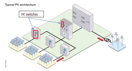
In DC applications such as battery storage systems or PV systems we usually meet also DC switches.
International Standard IEC 60364-7-712 requires device for disconnecting the inverter from both sides. Moreover, the standard specifically demands a switch-disconnector to be provided on the DC side of the PV-inverter. This allows the disconnection and reliable isolation of the inverter from all DC sources. Additional switch equipment can be used for disconnecting parts of the PV-array, for system earthing or for switching possible energy-storage circuits.
Meaning of load break switch disconnector can be explained by standard IEC60947-3 (Switches, disconnectors, switch-disconnectors and fuse-combination units). Switch is mechanical device that makes, breaks and carries current under normal conditions. Switch must be able to withstand making short circuit current but not breaking it. Another important definition is switch disconnector, which in the open position ensures isolating function. If we conclude above explanations, then load break switch disconnector is mechanical device that makes, breaks currents in normal circuit conditions, while in open position provides contact distance big enough to ensure isolating function. Isolating function ensures reliable disconnection of the circuit or part of it from power supply to provide safety.
Load break switch IEC symbol:
| switch + | disconnector = | switch disconnector |
 |  |  |
The selection of appropriate switch for a specific application must be done by considering important electrical parameters such as rated operational voltage Ue and rated operational current Ie. For multiple switches, Use is defined as the voltage between poles, while Ie is defined by utilization category which defines the type of load and frequency of use (nr. of cycles). The utilization category is divided by the current form on AC or DC applications. After the current form marking follows number which defines the type of load, then after letter A or B, which defines the frequency of use, therefore A is for switches that are used more frequently and B for less frequent operations. Frequency of use is given as the nr. of cycles per hour, nr. of cycles per lifetime and is dependent on Ie. For example: By the definition from standard switch with Ie=100A, the frequency of use A has total nr. of operations 10.000 cycles even under load Ie or no-load conditions while B offers only 2.000 cycles. But for both is limit 120 cycles per hour.
Most important DC Utilization categories
| Current form | Frequency of use | Type of load (application) | |
| A | B | ||
| DC | DC-20A | DC-20B | Connect and disconnect under no-load conditions |
| DC-21A | DC-21B | Switching of resistive loads, including moderate overloads | |
| DC-22A | DC-22B | Switching of mixed resistive and inductive loads, including moderate overloads | |
Characteristics of the switch are much dependent on technology (a mechanism) and used materials. For the housing are usually used plastic materials as an insulating material that retains current-carrying parts. That’s why plastics must be resistive to abnormal heat and fire to a certain level such as glow wire test 960 ⁰C. Also important is the color of the housing, it is easier to notice traces of heating and aging the material on light color housing (white), which can be the first sign to predict maintenance before complete failure occurs.
Each supplier has different technology, switching mechanism, but most common are next:
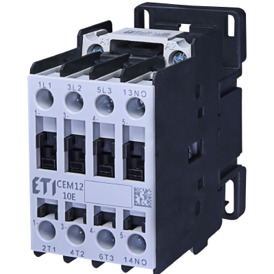
- Alloy pressure contact mechanism is known also as contactor type. The principle is that one side of contacts is pressed on the other side
- Sliding contact mechanism, can be rotational or moving bar
Both technologies have two parts of the mechanism fixed part and moving part of contact. Fixed part is directly connected with external contacts used for electrical wiring. Moving part is connected with handle thru spring mechanism that provides pressure and proper moving speed when breaking and making contact, important to extinguish electrical arc which directly influences on contact degradation and lifetime of switch. Switches intended for high current circuits very often contain arc chamber that splits electrical arc when breaking the circuit under load and helps to extinguish it.
Sliding mechanism:
Both switching technologies ensure double break per pole, which means that switch makes and breaks contacts in two points, which gives more secure operation and longer distances to assure insulation function.
Things get complicated as we control DC currents. While at AC current there is always 10ms zero crossing (50Hz sinus), at DC current is permanent. Therefore, problem appears with interrupting the arcing, while at AC is self-interrupted (zero crossing), at DC must be managed artificially. Arcing can be shut down with distance or with barrier. That’s why majority of PV switches on the market are multipole, with poles connected in series you get longer distance to split the arc. Higher the voltage, higher number of poles. At LBS DC switches there is distributed 500V per pole, for 1000 V DC 2 pole switch is used, while for 1500V DC 3 pole switch is used. At such a high-voltages, creepage distances is also important, to prevent breakdown between poles. There-fore LBS DC switches have increased distance between poles to not only 25mm as demanded by IEC standard, but 53mm, which ensures also UL compatibility (demand for 50mm distance).

a) 2 poles in series (500V/pole), b) 4 poles in series (250V/pole), c) 3 poles in series (500V/pole)


Catalogue |