


High-voltage (HV) fuses in particular applications
Summary
HV fuses, often named also HH fuses are High-voltage High-rupturing capacity fuses designed for alternating voltages >1 kV.
Protection of transformers for power distribution networks is the most widely spread application of HV fuses. With only a few exceptions back-up fuses are used for short-circuit protection of the primary side of power transformers. As international standard IEC 60282-1 and the harmonised German Standard VDE 0670, Part 4 do not specify any time-current characteristics for HV fuses, and even rated currents are only defined by the specified temperature rise of the contact pieces. Thus, rated currents of HV fuses from different manufacturers cannot directly be compared to each other. Selection of such fuses is based alone on manufacturer’s data. The purpose of this article is to show to the readers proper principle of MV Back-up fuse-link selection for power transformer protection.
Viktor Martinčič Product manager for fuse systems, Chair of IEC technical committee for fuses TC 32 |
Keywords
High-voltage-Fuse, Current-Limiting Fuse, Back-up Fuse, Power transformer

General
Fuses have been in use since the very beginnings of electrical power distribution. While the true inventor of the fuse is not known, pioneers of electrical distribution soon incorporated them as "weak points" in their circuits to prevent overheating of wiring, due to excessive current, and to prevent damage to fragile lamps from fluctuations in voltage. Fuses rapidly developed into devices able to sense a current higher than normal and quickly interrupt (break) that current, all in a self-contained easily replaceable unit. Although the variety and complexity of fuses has grown to the point where user’s guides, such as this one, are necessary, fuses still provide the highest degree of protection for the lowest initial cost.
The simplest definition of a "fuse" is that it is a device that carries current through a conductive part called the fuse element that, when the fuse is subjected to an excessive current, melts due to self-heating and initiates the interruption of the current. All conventional fuses interrupt current after some arcing across breaks in the element produced by the melting process. The melting time of a fuse is therefore also termed the "pre-arcing" time. A characteristic of fuses is that, because current interruption is initiated by a melting process, there are almost no "mechanical" aspects involved in their arc initiation. Fuses therefore have a very inverse time-current relationship (higher currents giving shorter pre-arcing times). This enables extremely short pre-arcing times at high currents, virtually without limit. It is this apparently simple phenomenon that is primarily responsible for the universal success fuses have enjoyed for a very long time.
In general, high-voltage fuses (defined as fuses rated above 1.000 V a.c.) are physically larger and generally more complex than low voltage fuses due to their need to operate at much higher voltages. HV fuses may perform one or both of two primary functions.
The first function is to respond to moderately excessive currents, typically termed "overload" currents. In this case, the rated current of the fuse (the current it is designed to be capable of carrying indefinitely without deterioration) is exceeded by a relatively modest amount (typically less than 10 times). Such currents can be caused by too much load being connected to a circuit, or by a fault that by-passes only part of the load. It should be noted that not all types of fuses are designed to have the ability to operate successfully if melted by a very low overcurrent as some types are intended only for operation at high currents.
The second function, which virtually all fuses are designed to perform, is to respond to overcurrents that are much higher, and that are usually termed "short-circuit" currents. In this case substantially all of the load is by-passed by a major fault and the available current (which, when not limited by a protective device, is termed the "prospective current") can be very high. However different types of fuse vary widely in exactly how high a current they can interrupt, and this may be a significant factor in choosing a fuse type for a particular application. The ways in which fuses respond to high and low over-currents, as well as the ways in which they actually interrupt the current, causes HV fuses to be classified in various ways.
The first main classification is into "current-limiting" and "non-current-limiting" types. "Current-limiting" (CL) describes a class of fuses defined by the behaviour that occurs when the current is so high that the fuse element melts before the first peak of the fault current (that is in less than a few ms ). Upon melting, this type of fuse introduces resistance into the circuit so rapidly that the current stops rising and instead is forced quickly to zero (before a natural current zero would occur). Because the maximum prospective peak current is not reached, the fuse limits the current in magnitude as well as duration hence the 3 "current-limiting" name. Note that during operation, the current-limiting fuse introduces a "spike" of overvoltage (the fuse switching voltage) into the system during the currentlimiting action.
An “non-current-limiting” fuse, usually named expulsion fuse, melting under the same circumstances, introduces only a small resistance into the circuit, so the current continues to virtually the same peak as would occur if the fuse had not melted. An expulsion action (that is where gas is generated by the arc and expelled along with ionized material) produces a physical gap such that, at a natural current zero, the arc does not reignite and the current is interrupted. This type of fuse therefore limits the duration of a fault but not its magnitude.
Current-limiting back-up HV/HH fuses
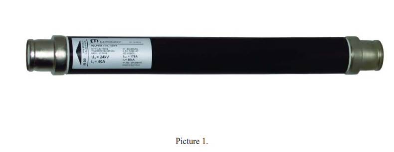
At high currents HV back-up fuses function the same way like low-voltage high-rupturing capacity fuses, usually called NH fuses (German: Niederspannungs-Hochleistungs), see picture 1.
They, however require significantly more element restrictions in series, the number of partial arcs being increased accordingly, due to the high recovery voltage. The fulgurite winds around the insulating core, following the way of the fuse-element. The longer the arc burns, the thicker the fulgurite will become. That is why the distance between the individual turns of the fuse-element must be sufficiently dimensioned to allow the switching arc to follow the turns instead of moving in a straight line in longitudinal direction. Also the distance between the fuse-element and the fuse tube must be sufficiently dimensioned to prevent the fulgurite from getting into contact with the inner wall (of the tube) and the tube from bursting, due to significant difference in temperature. Sufficiently high switching voltages for an effective current limitation come into existence through the interdependent functioning of high pressure and intensive cooling by the melting sand. High short-circuit currents generate high pressure in the fuse tube (up to 100 bar) and have a promotional effect on the breaking process. The breaking capacity is only limited by the pressure resistance of the fuse body.
The maximum breaking current I1 required to be printed on the fuse has to be larger than the maximum short-circuit current expected to be encountered in service. In order to ensure ideal conditions for proper operation, a minimum breaking current is required for the inner pressure of the fuse to reach a sufficiently high value. HV back-up fuses are not capable of clearing lower currents. If the restrictions of the fuse- 4 element melt at a current that is smaller than the minimum breaking current, the arc would burn for so long, until the sand melts and the porcelain tube gets destructed. Subject to the mounting conditions, the above mentioned may result in severe consequences.
The minimum breaking current I3 required to be printed on the device is one of the characteristic ratings of a fuse. For currents below I3, known as the “prohibited range”, time-current characteristics are marked in dashed-line style to show that, even though the fuse-element melts, the fuse will not be capable of breaking the melting current. If currents are expected to be encountered at the place of installation of the HV back-up fuse which are within the dashed-line range of the time-current characteristic, additional protective devices must be provided such as switch-fuse combinations which are designed to interrupt such currents.
Distribution transformer protection with current-limiting fuses
Purpose of fuses
It should be remember that the primary purpose of a transformer fuse is to remove a faulted transformer from the power system and minimize the risk of an eventful failure. Protection of the system, and minimization of the extent of the area affected by a fault, is therefore a significant concern. An "eventful" transformer failure is one that results in external damage that might be a risk to persons or property. In addition to these primary benefits, fuses can, under certain circumstances, also provide overload or secondary short-circuit protection for the transformer. While this is normally provided by secondary protection, it is sometimes required from the primary fuses (sometimes as "back up" to the secondary protection). Some desirable protection characteristics to be considered in selecting fuses for transformer applications are listed; however, it should be borne in mind that some of these requirements may be contradictory, in which case the user’s priorities should be taken into account:
a) to protect the distribution system from the effect of faults at or within the transformer, and coordinate with the next upstream overcurrent protective device up to the maximum fault current available at the transformer fuse
b) to provide the best possible protection to the transformer from damaging through-faults (the current flowing through the transformer from a secondary fault, outside the transformer). The degree of transformer protection is determined by comparing the operating time-current curve for the selected fuse with the appropriate transformer short- time loading curve. Both curves need to be properly adjusted to reflect differences between primary- and secondary-phase currents and winding currents associated with the specific transformer connection involved and the types of possible faults in the secondary circuit
c) to provide detection and isolation of internal transformer faults and reduce the possibility of transformer case rupture
d) to permit loading the transformer to the maximum loading practice of the user
e) to withstand combined transformer magnetizing inrush and load pickup current after shorttime (up to 1 min) service interruption, and combined transformer magnetizing inrush and load pickup current after extended (30 min and longer) outages 5
f) to properly coordinate with overcurrent protection devices on the secondary side of the transformer
g) to withstand surge discharges through a transformer with an earthed primary winding that experiences saturation of its magnetic circuit by a lightning-induced surge voltage with a long time wave shape (primarily with small transformers 25 kVA and lower)
h) to withstand surge currents that may be discharged through an arrester located on the load side of the fuse and ahead of the protected transformer.
Inrush considerations
Fuses may be subject to damage if inrush currents cause partial melting of the fuse element(s). Inrush currents due to energizing a transformer can be high and require checking as part of the normal selection and coordination procedure.
When a transformer is energized, relatively high inrush currents may occur, depending upon the residual flux in the core and the voltage at the instant of closing the circuit. Tests with typical transformers, as well as many years of experience in applying both current-limiting and expulsion fuses for transformer applications, have produced a generally accepted set of guidelines for fuse selection. These guidelines consider the typical first loop current value, as well as the r.m.s. value over the duration of a typical inrush current. The guidelines are in the form of two time-current points, and are expressed as multiples of transformer rated full-load current. The transformer manufacturer's guidelines should be followed if available, but typically the values used are 25 times rated current for 0,01 s (North American practice) and/or 12 times rated current for 0,1 s (universal practice). Different values may be applied based on transformer size and design. These points are compared to the fuse’s minimum prearcing TCC. If at these points, the fuse characteristic lies above and to the right, then the fuse is considered to be capable of properly withstanding the magnetizing-current inrush of the transformer
General rules
Current-limiting fuses are commonly used to protect transformers. There are two common methods of protecting transformers based loosely on "European" practice and "North American" practice, although there are many parts of the world that use one, or both, of these practices. IEC standards recognize "European practice" and "North American practice" in terms of preferred voltages and insulation levels; therefore these terms will also be used in relation to transformer protection practices, while recognizing that such practice is not unique to either area. While there are many reasons why one or the other practice is adopted, one of the driving forces is the density of utilization. Where many customers are concentrated in a particular area, larger sized transformers used with ring main units (incorporating switch-fuse combinations, with the switch tripped by the Back-Up fuse striker, or circuit-breakers) are often more economical. This is "European" practice. Where customers tend to be more spread out, it is more common to provide a small number of households (often one) with an individual transformer. This makes the switch-fuse combination impracticable. Instead, either a FullRange fuse is employed, or a combination of Back-Up fuse and expulsion fuse provides the full-range capability. This is "North American" practice, and such a combination of fuses poses special coordination requirements.
Fuse-link time-current characteristics
The time-current characteristics of HV fuse-links for transformer circuit applications should have the following features:
a) relatively high operating current in the 0,1 s region so as to withstand transformer inrush current and give good coordination with protection devices on the secondary side (where fitted)
b) relatively low operating current in the 10 s region so as to:
• ensure rapid clearance of transformer winding faults, secondary side faults and, if applicable, primary side earth faults
• give good coordination with up-stream overcurrent protective devices (source side).
Therefore, the pre-arcing time-current characteristics of fuse-links for transformer circuit applications should preferably be within the following limits:
If10 / Ir ≤ 6
to fulfil condition b)
If0,1 / Ir ≥ 7*(Ir / 100)0,25
to fulfil condition a)
where, all current values being expressed in amperes,
Ir is the rated current of the fuse-link;
If10 and If0,1 is the pre-arcing currents corresponding to 10 s and 0,1 s respectively, expressed as mean values with the tolerances specified in 4.11 of IEC 60282-1:2009.
The term (Ir /100)0,25 is introduced to take account of the fact that the pre-arcing time-current characteristics for a range of fuse-links diverge as they approach the short-time region.
Coordination
The following picture illustrates a typical transformer application involving a high-voltage fuse-link (or fuse-links), a transformer and possible protective devices on both source and load sides
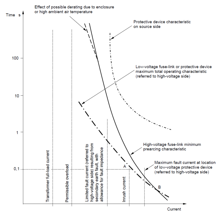
Picture 2 – Characteristics relating to the protection of the HV/LV transformer circuit
The transformer will be chosen first for its particular duty. This establishes the value of the rated current of the transformer, the value of the permissible overload current (where applicable) and also by inference, the inrush current. The HV fuse-link(s) are then chosen so as to give optimum protection to the circuit, bearing in mind the factors of Items a) to d) listed below.
With reference to Picture 2, the following should be noted:
a) the primary side HV fuse-link minimum pre-arcing time-current characteristic should be to the right of point A defining the transformer inrush characteristic. For practical purposes this may be taken as approximately 12 times the transformer rated current for a duration of 0,1 s 8
b) the rated current of the primary side HV fuse-link should exceed the rated current of the transformer:
• by an amount sufficient to allow for permissible overloading of the transformer under service conditions (refer to IEC 60076-7 and IEC 60076-12)
• by a further amount where the fuse-link(s) are mounted in an enclosure so as to ensure that the specified temperature limits for fuse-links are not exceeded and so that excessive fuse element temperature does not lead to premature fuse operation
• by a further amount where the ambient air temperature is likely to exceed that specified in Clause 2 of IEC 60282-1:2009
c) the pre-arcing current of the primary side HV fuse-link should be as low as possible in the 10 s region of the fuse time-current characteristic in order to ensure the maximum protection of the transformer
d) for complete coordination between primary side and secondary side fuse-links or other protective devices on the load side, the intersection B of the primary side time-current characteristic (minimum pre-arcing) and the secondary side device characteristic (maximum operating) (as referred to the primary side taking into account the appropriate ratio) should occur at a value of current greater than that of the maximum fault current on the load side of the secondary side protective device.
Finally, where it is seen that the desired degree of coordination has not been achieved, the selection or setting of the source side overcurrent protective device may be re-examined. Similarly, the maximum rating of the secondary side fuse-link(s) may need to be reduced for the same reasons.
Bibliography
[1] IEC/TR 62655 Ed.1, 2013-05, Technical report “Tutorial and application guide for high-voltage fuses”
[2] Dr.Ing. Herbert Bessei, FuseXpert, “Fuse Manual, Power fuses, Manual for users of low-voltage and high-voltage fuses”, NH/HH Recycling, 4.Auflage 2011
[3] ETI Izlake MV fuse-links technical informations