


Smart Motor Control: How to Reverse the Rotation Direction of a Three-Phase Motor Safely and Efficiently
Three-phase asynchronous motors are among the most widely used electrical machines in industrial and commercial applications. Their reliability, relatively simple construction, and efficiency make them suitable for conveyor systems, machine tools, pumps, lifting devices, and countless automated processes. In many applications, however, operation in a single direction is not enough. Equipment often requires movement in both directions, making motor direction control an important function of the system design. Let's look at how a classic forward/reverse control circuit works, which components are required, and how protection devices help ensure reliable operation.
Why Would We Need to Change the Rotation Direction?
Many industrial processes rely on bidirectional movement:
- Conveyor systems transporting material in both directions
- Hoists and lifting mechanisms
- Automated machines with forward and reverse motion
- Production systems requiring precise positioning
For a three-phase asynchronous motor, changing the rotation direction is achieved using a simple principle:
When any two phases are exchanged, the rotating magnetic field changes direction and the motor rotates in the opposite direction.
In the circuit described in the original design, phases L1 and L3 are exchanged to achieve the change in direction.
Although the principle itself is simple, reliable operation requires properly designed switching and protection logic.
Understanding the Circuit Structure
The system consists of two main sections:
- Power circuit
- Control circuit

Remote start and stop of a three-phase asynchronous motor with rotation direction reversal.
The power circuit delivers energy to the motor, while the control circuit determines how and when the motor operates.
Push-Button Control: Simple Operation for the User
Motor control is performed using push buttons:
S1 – Stop button
- Red button
- Normally Closed (NC) contact
- Stops motor operation
S2 – Start button (forward direction)
- Green button
- Normally Open (NO) contact
S3 – Start button (reverse direction)
- Green button
- Normally Open (NO) contact
To reverse the motor direction, the motor must first be stopped using the stop button and only then restarted in the opposite direction.
This sequence prevents unintended switching and helps ensure safe operation.
Why Two Contactors Are Required
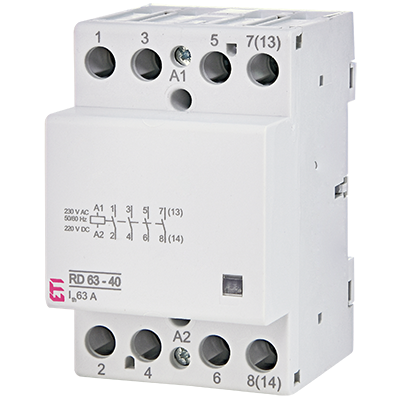
Since two different phase arrangements are needed, the system requires two contactors:
- K1 – operation in one direction
- K2 – operation in the opposite direction
These contactors act as electromechanical switching devices that remotely connect the motor to the power supply.
Because asynchronous motors generate high starting currents, contactors used in such applications should be selected according to AC-3 utilization category requirements.
The Role of the Control Circuit
The control circuit begins with a protective device:
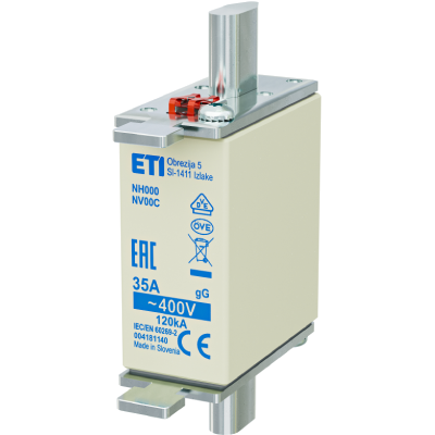
F3F control fuse
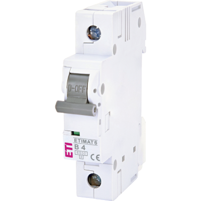
(or alternatively a miniature circuit breaker)
Its purpose is to protect the control circuit from short-circuit conditions.

Control circuit showing actual switching components.
The operating sequence is as follows:
- Voltage passes through the control fuse.
- The current flows through the overload relay contact.
- The stop button (S1) remains closed during normal operation.
- Pressing a start button energizes the corresponding contactor coil.
- Main contacts close and connect the motor to the power supply.
The contactor coil in this example operates on 230 V AC, although many applications also use 24 V DC control voltage systems.
Self-Holding Contacts: Keeping the Motor Running
One important feature of contactor-based control systems is the self-holding function.
When the operator presses the start button:
- The contactor coil becomes energized
- Main contacts close
- The motor starts operating
- An auxiliary NO contact closes simultaneously
This auxiliary contact creates a parallel path around the push button and keeps the contactor energized even after the button is released.
This arrangement is called a self-holding contact.
Without it, the motor would stop immediately after releasing the start button.
Electrical Interlocking: Preventing Simultaneous Operation
Imagine what could happen if both contactors activated at the same time.
Since both contactors create different phase arrangements, simultaneous operation could lead to serious electrical faults.
To avoid this, the circuit uses electrical interlocking.
Normally closed auxiliary contacts:
- K1 (21–22)
- K2 (21–22)
prevent the second contactor from operating while the first one is active.
This safety mechanism ensures:
✔ Only one direction can be active at a time
✔ Equipment protection
✔ Increased reliability
Understanding the Power Circuit

Power circuit of the forward/reverse motor control system.
The power section begins with:
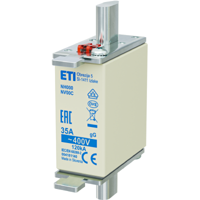
F1F protective fuses
(or alternatively type C miniature circuit breakers)
The current path is:
L1 → L2 → L3 → F1F → contactor → overload relay → motor
The motor must also be connected to protective earth (PE conductor), while a neutral conductor is not required.
Protecting the Motor from Overload Conditions
Motor protection is essential because overload conditions increase current beyond the motor's rated value.
Excessive current can result in:
- Increased temperature
- Reduced service life
- Damage to insulation
- Motor failure
To prevent this, the circuit includes a bimetal overload relay (F2F) adjusted according to the motor's rated current.

Overload relay
When overload occurs:
- The overload relay detects excessive current.
- Contact 95–96 opens.
- The control circuit is interrupted.
- The motor stops immediately.
How Fast Does the Overload Relay React?
The tripping speed depends on the magnitude of overload current.
The article's time-current characteristic shows that:
- Higher overload current results in faster disconnection
- Lower overload levels result in slower response

I-t characteristic of an overload relay
For example:
If the relay is set to 10 A and current rises by 50%, the relay may trip after approximately two minutes, while a preheated relay can react even faster.
Modern Alternatives
Traditional motor protection often combines:
- Fuses
- Contactors
- Bimetal overload relays
Today, many installations replace the fuse and overload relay combination with motor protection circuit breakers, simplifying the system while maintaining the same control principle.
Conclusion
Reversing the rotation direction of a three-phase asynchronous motor involves much more than simply swapping two phases. Reliable operation depends on a coordinated system of control devices, contactors, interlocking functions, and protection mechanisms.
When these components work together correctly, the result is a system that offers:
- Safe operation
- Reliable motor control
- Equipment protection
- Reduced downtime
- Long-term operational efficiency
Understanding these principles helps engineers and technicians design systems that perform reliably in everyday industrial environments.