Type some words to find content.
eg: fuse, arrestor, 00110115 technical, MCCB...
Recent searches
Tehnical support
This email address is being protected from spambots. You need JavaScript enabled to view it.
Unleashing the Power of Mode 4 Charging: Safeguarding Your EV

Unleashing the Power of Mode 4 Charging: Safeguarding Your EV

Unleashing the Power of Mode 4 Charging: Safeguarding Your EV


Charger fuse for protection of highpower DC EV chargers

Safety is our top priority when it comes to Mode 4 charging systems. That's why our Charger fuse plays a vital role in safeguarding DC circuits, capable of handling voltages up to 1000V DC and rated currents up to 600A. These specially designed fuses feature unique dimensions and connection contacts tailored to meet the specific requirements of each charging application.


Anže Jerman

Product manager

Photovoltaic String Protection: Keeping the Current Flowing Safely

Photovoltaic String Protection: Keeping the Current Flowing Safely

Photovoltaic String Protection: Keeping the Current Flowing Safely


Photovoltaic 1500V d.c. systems

With the PV String protection, we have in mind the protection of PV modules against reverse currents. It is used in combination with central inverters where PV strings are usually combined in d.c. combiner boxes. Inside d.c. combiner boxes, PV strings are protected with cylindrical fuse‑links inserted in cylindrical fuse holders. 


Anže Jerman

Product manager

E-mobility: Electric chargers - part 2

E-mobility: Electric chargers - part 2

E-mobility: Electric chargers - part 2

The most efficient and safest method for charging electric vehicles for home use in accordance with the IEC 61851-1 standard is AC mode 3, either a single-phase or three-phase connection with different power ratings.


Aleksander Cilenšek
Product manager
E-mobility: Electric chargers

E-mobility: Electric chargers

E-mobility: Electric chargers

E-mobility is booming; alongside electric scooters and bikes, we are also seeing more and more electric cars. There are several types of hybrid electric vehicles on the market: hybrid electrical vehicles (HEVs), plug-in hybrid vehicles (PHEVs) and battery electric vehicles (BEVs).


Aleksander Cilenšek
Product manager
Photovoltaics Array protection

Photovoltaics Array protection

Photovoltaics Array protection


When we talk about photovoltaic installations for voltage up to 1500V DC, we can mean different types of solutions and ways to implement them in reality. There are several ways to convert DC voltage to AC voltage.


Anže Jerman

Product manager

Suitable protection for motor drives

Suitable protection for motor drives

Suitable protection for motor drives


In today’s industry avoiding “down-time” can be the same as creating income

The upper statement ever more reflects the current conditions in the industry. Reliability ofproduction systems is becoming more and more important and will even more do so in thefuture. We all wish for our production devices to be functioning normally. But if amalfunction appears, it should be fixed as soon as possible, for every hour of down-timepresents a loss of income. Despite many designers’ opinion that one can protect motordrives using only miniature circuit breakers, experiences show that internal part offrequency converter remains unprotected from short-circuiting.

Keywords: soft starter, frequency converter, IGBT, semiconductor protection fuses.

Brane Lebar

Specialist of product group

Fuses for DC voltages DC and PV – DC-voltage fuses and Photovoltaic fuses

Fuses for DC voltages DC and PV – DC-voltage fuses and Photovoltaic fuses

Fuses for DC voltages
DC and PV – DC-voltage fuses and Photovoltaic fuses


Introduction


We know fuses and "fuses". The consequence of using a incorrect electric fuse in an incorrect electric circuit can cause its explosion and/or the destruction of neighbouring appliances. Greater consequences can occur in the case of destruction of protected appliance –transformer, inverter or the damaging of electrical installation. In the article we will present the problem of activity of fuses in DC electrical circuits as well as several examples of usage of
fuses in photovoltaic systems connected to the public grid.


Viktor Martinčič

Product manager for fuse systems, Chair of IEC technical committee for fuses TC 32 

Why should we use a fuse at all?
A fuse is only one of many devices in electrical installation which are as a "sacrificed" element incorporated in the electric circuit. Fuses are designed in such a way so that they can interrupt electric circuit if excessive electric current appears in it. This can occur because of overloading or any other defect. In this way, with the interruption of the circuit further injuries of other elements of the circuit which could occur if the protecting device would not be included / comprised – in this case the fuse. As it has already been mentioned, the fuse is in a way sacrificed because it is destroyed and it has to be
replaced.


The properly chosen fuse can prevent fire or the remaining damage when the connection cable contacting unpredictably impairs (for example in electric circuit photovoltaic module - inverter), if the connection cable distribution board suddenly comes in a contact with earth terminal, if it comes to the short circuit because of the fallen screw or/and if the destruction of isolation and consequently short circuit are caused by animals.

It is generally known that in the case of long-continued overloading or short circuit caused in any kind of way the melting element inside the fuse blows out. At the same time, if the connection cable is correctly calculated (its ampacity has to be higher than the nominal fuse current), the fuse will operate in time and in this way it will prevent the isolation from burning and further damage.

Categorization of fuses
The fuses are categorized according to the rated current, nominal voltage, rated breaking capacity and also if they are appropriate for usage in electric circuits with alternate current (a.c.) or direct current (d.c.).


Rated (nominal) current of the fuse is the value of the current which can carry continuously without deterioration under specified conditions.

Rated (nominal) voltage is the value of the voltage with which the fuse can extinguish the existing arc without influencing the surroundings.

Rated breaking capacity is a value of prospective current that a fuse is capable of breaking at a stated voltage under the prescribed conditions of use and behaviour.


Are AC and DC fuses the same?

No, they are not. Theirs fusible elements, as most important parts of each fuse are differrent. When we compare the ability of interrupting AC and DC currents we should be aware that at AC conditions the value of the current is more ten times in a second crossing through zero value and here is the ability to extinguish the electric arc made easier.

The interruption of the DC current occurs much difficulty and the reason for that is that short-circuit current flows only in one direction up to arc extinguishing is achieved.
The melting element in DC fuses has to be designed in order to interrupt the current in the electric circuit with the “sufficient power” if too high current flowing too long. This should occur inthe shortest time possible in order to extinguish the electric arc that occurs at that moment.

DC fuse-links are relatively complexed elements which contain a great deal of interacting particularities. Because of that the price of DC fuse-link is slightly higher that ordinary links. Some of fuse-links are marked as AC and as well with DC permissible value of nominal voltage.
Low voltage fuses (fuses used mainly for industrial use, see standard IEC 60269-2, Ed.3, 11/2006) have minimum defined breaking capacity 50kA a.c. and 25kA d.c.
Breaking capacity of the fuses in electric circuit with greater time constant (where great d.c. motors are used for instance) should be appropriately adapted – derated. Of course it is also affective the other way round - in networks in which great inductivity is not expected, such as in battery power feeders, we can also expect greater breaking capacity as nominal.


The breaking capacity of the fuse-link has to be looked upon from the viewpoint of time constant which applies to the electric circuit discussed at the moment.


More detailed information are generally supplied by the fuse-links manufacturer’s or they can be defined and proved by testing. It depends on the manufacturer whether it tests its products only on AC voltages (which is usual) or also on DC.


On the pictures 1. and 2. tables of standard tests for NH fuse-links are presented, separately for DC and AC voltage (see IEC 60269-2) In the table on the first picture additional requirementsfor the value of time constant (inductivity) of DC electric circuit is given. The value has to be between 15 and 20 ms.


What is influence of the time constant on the electric circuit?
In practice protective device, such as circuit breakers or fuse-links, can work irregularly if the time constant (industiviry) of the electric circuit is too high. In other words, the protective appliance can not extinguish the arc… !
The time constants that are too high can be very inconvenient for the accurate operation of the protective devices. Problems can also occur at lower voltages as nominal and short-circuit currents that are smaller than nominal breaking capacity of the protective appliance.


As the length of the connection cable grows the resistance of the electric circuit also increases. As the distance between parallel connection cable (positive and negative pole) grows, the inductivity grows as well. Similarly, it also occurs with capacitivity but its value does not flow uniform.
The three factors mentioned (resistance - R, inductivity - L, capacity - C) determine the time constant T of the electric circuit which is expressed in units ms (millisecond). We have to pay special attention to the method of practical assembling of all the elements in the electric circuit.


Are DC fuses useful also in the field of renewable energy sources?
Yes, it is one of the most developing areas and one of the most important areas of electrical energy production is undoubtedly solar (photovoltaic PV) energy production. Electrical energy is produced in Solar plants, where a semiconductor solar cells convert sun light directly into
electrical energy.


The electrical installation drawing (scheme) of the standard photovoltaic system which is connected to the fixed electric power network is shown on the picture 3. In the continuation the elements of the photovoltaic systems will be defined as PV (from the word Photo Voltaic), so PV fuses, PV modules, PV system, etc.


 The usage of fuses in PV systems is different. It mostly depends on the regulations and technical practice of individual state. In USA, Canada and Mexico they mostly stick to document- regulation titled »Photovoltaic Power Systems – Suggested practices« when designing PV systems. The document was prepared by NEC (National Electrical Code).


It is OBLIGATORY to use PV fuses in all PV systems that are connected to the public electric power network. The situation in Europe is rather different.

While in Germany people are quite skeptical when it comes to using special fuses for PV systems, the situation in Spain and Italy is rather different. After having problems which occurred in the past (the destruction of the installation and distribution box – look the following pictures no. 4. and 5. and 6.), they decided that the use of fuse-links is OBLIGATORY.

 Before we will continue with the description of short-circuit protection of PV systems we shall shortly describe the function of of solar installation components.
To produce electrical voltage (energy) from the sun’s energy we use semiconductor (mono- crystal or poly-crystal) silicon’s solar cells, which generate the electrical voltage if they are exposed to sunlight.


The solar cells of the size 12,5 x 12,5 cm generate with approximately from 0.6V voltage and up to to 3,5A electric current. To achieve higher voltage we should connect solar cells in serial connection. Such connected solar cells are named “PV modules” see picture 7.


 They are already composed at the manufacturer’s of PV modules where several modules are electrically connected and they reach the surface from 1,5 to 2,5 m². Such a module generatesfrom 30V to 60V DC voltage.
The achieved voltage of one module is approximately 30V d.c. This voltage is constant and is changed only in case when sunlight does not reach PV module. Module also generates output current which values are from 4A to 7A, depends from the type of the PV module. For achieving higher currents, PV modules should be connected in parallell –we get »strings« and gained outout currents in the rank from 25A to 35A.
This current is then connected to the »DC/AC inverter«. It is electronic device which convert DCcurrents (voltage) to AC current (voltage) – see picture 4. AC current/voltage is transmitted into the public electro energetic network over remaining elements – galvanic isolated transformer, electrical metering system and main circuit breaker.

In the picture no. 3 it is shown that more modules are connected in the series. Example of PV distribution box is presented on the picture 8.

An example of two levels of protection in PV systems:
1 st The level of protection is used specially for disconnection of DC short circuits in the area of panels – right next to the solar fuse-links (further on CH10 gPV) placed into cylindrical disconnector type PCF DC (see picture 9).


The first level enables physical and electrical separation of each individual panel. It is important to emphasize that the discoonnector is placed on the positive and as well as on the negative pole. Our example on the picture number 9, seven modules are connected into the panel. For their short circuit protection is necessary to have 14 PCF DC disconnectors where suitable CH 10 DC fuse-links with gPV characreristic are placed.

2 nd The level of protective fuse-links is usually located near the entry of the invertor’s connection and is electrically connected with the cylindrical disconnectors from the first level. The fuse-links, usually NV DC with nominal DC voltage 750V or higher are placed near the NH disconnector which enables safe and quick electrical separation of the invertor and the entire unidirectional part with PV panels.


On this level NV DC fuse-links with DC voltage 750V up to 1.100V d.c. are used. They are also in the production range of ETI d.d. The introduced example is, of course, not the only one, others will be described in the future articles.


Sources:

  • NEC »Photovoltaic Power Systems – Suggested practices«
  • Internal ETI reports and knowledge
  • Code Corner – Photovoltaic Systems Assistance Center, Sandia National Laboratorie
USE OF RCBO AS  ADVANCED PROTECTION IN LOW VOLTAGE   ELECTRICAL INSTALLATION

USE OF RCBO AS ADVANCED PROTECTION IN LOW VOLTAGE ELECTRICAL INSTALLATION

USE OF RCBO AS ADVANCED PROTECTION IN LOW VOLTAGE ELECTRICAL INSTALLATION


Abstract: 

RCBO is an abbreviation for Residual Current circuit Breaker with integral Overcurrent protection. Basically is a combination of two products, namely a MCB-Miniature Circuit Breaker and RCCB- residual Current Circuit Breaker. In this article basic information about the RCBO is explained, as well as an application and use of RCBO’s in modern low voltage electrical installations. This article has no intention to make a detailed explanation of content of IEC product standards, but to provide more practical information how and where to use RCBO as an advanced protection in modern low voltage electrical installations.


1. Introduction

In general, in low voltage electrical installation, two basic protections must be provided. Firstly, protection of cables and other conductive parts against overheating, followed by the overcurrent, and secondly, the protection of people against electrical shock in case of touch of live parts, where the live parts are meant as parts under voltage.


Msc.Mitja KOPRIVŠEK

Bsc.el.eng.


2. Use of MCB’s

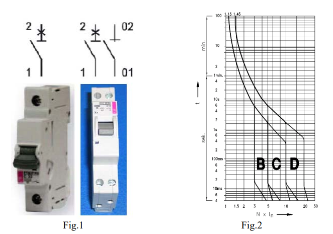
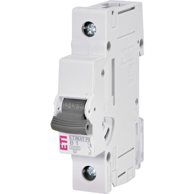
Since many years, the protection of cables against overheating and protection of people against electrical shock in case of indirect touch of live parts, is provided with MCB’s. Fig.1 shows two typical representatives of MCB’s, namely, one pole MCB with rated current from 6A up to 63A, and one pole plus neutral also in one module width of 18mm. On the same figure Fig.1 we can also see the wiring diagram. Important technical information of MCB is time-current characteristics according to international standard IEC 60898. A graphical expression of such characteristics, called also B, C and D characteristics are shown below on Fig.2


 In general, time-current characteristic covers all areas of overcurrent: 

2.1. Overload,

- which protects the conductors and cables according to their current-carrying capacity,

- It is important to know that all three, B, C and D characteristics has the same behaviour in overload area. This behaviour is in line with current-carrying capacity of the conductor, as described in standard IEC 60364-5-52. Conclusion: MCB’s according to IEC 60898 are very much suitable for conductor overload protection.

- Practical recommendations:

   o For protection of 1-phase cable (two loaded wires), cross-section of the conductors 1.5mm2 and 2.5mm2, we can use following MCB’s as overload protection devices:

       - For 1.5mm2 in most cases we can use MCB with rated current 10A or 13A, depends on insulation material and the type of the cable or conductor 

       - For 2.5mm2 in most cases we can use MCB with rated current 16A or 20A, again depends on insulation material and the type of the cable or conductor.


 2.2. Short circuit:

- Short circuit behaviour of MCB is used for protection function called “Automatic disconnection in case of fault”, shortly also called “fault protection”.

- All technical conditions for successful and effective fault protection is prescribed in a standard IEC 60364-4-41, important data is an impedance of the fault loop,

- MCB with B characteristics provides immediate disconnection if the fault current gets the value of 3times to 5 times of MCB rated current, and MCB C provides the disconnection in range of 5times to 10 times.

- Recommendations:

   o for installation branches with non-inductive loads (lighting, heaters, etc.) , B characteristics is acceptable,

   o For installation branches with loads with high in-rush currents, (electric motors, transformers, power tools, hoovers, etc.,) we strongly recommend C characteristics, in some cases even D characteristic.

   o Use of MCB with minimum 6kA short-circuits capacity and current limiting class 3.

 - Explanation:

   o MCB with C characteristic breaks the current instantaneously in case of actual current in value between 5times up to 10 times of rated current. In practice, break current value is set up in the middle of the range, around 7 times of rated current. In case of in-rush current of 8times of rated current and more, the MCB will trip and this will be the appearance of unintentional tripping or so called nuisance tripping.

   o In case of use of B characteristic, such nuisance tripping will occur more often and normal use of electric energy will be disturbed,

   o By using the MCB C characteristic, such nuisance tripping will be decreased to zero. 


3. Use of RCCB’s in fault protection


Residual Current Circuit Breaker RCCB’s technical principle is based on residual current transformer which is capable to identify very small value of fault current which flows from the location of fault through the fault loop and PE conductor. “Fault protection” is often called also as “Protection against indirect touch of live parts”.


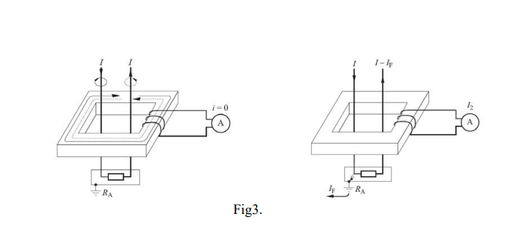
The Fig.3 below shows the basic principle how it works: - if there is no fault, the incoming and outgoing current are the same and there is no secondary induced voltage and therefore no trigger current to open the RCCB, - if there is a fault in the appliance, then very small difference between incoming and outgoing current can induce secondary voltage and thus provoke the trigger process of RCCB.

The requirements for RCCB’s are given in standard IEC 61008 and there is wide range of products explained and prescribed. The main criteria of classification are:

- Nr of poles: 4p, 2p

- Rated current: from 16A up to 63A, and up to 125A - Type of residual current:

   o sinus 50Hz: AC type,

   o sinus 50Hz and DC pulsating: A type

- Rated residual current: 10mA, 30mA, 100mA, 300mA, 500mA

- Breaking times: instantaneous, time delayed also called selective.

RCCB’s are widely used as fault protection in TT, TN-S, TN-C-S and IT systems. RCCB’s must not be used in TN-C systems, where the N-neutral and PE-protective earth conductor are common in only one PEN conductor.


3.1. RCCB:

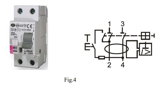
On the Fig.4 below there is a practical example of an RCCB 2 pole, Atype 30mA, most used in fault protection in one phase residential electrical installation. The rated current is usually 16A, 25A, 40A, 63A, and even 80A. Fig4 is also equipped with wiring diagram. It is clearly seen that RCCB provides only fault protection and no over-current protection.


4. Additional protection in case of direct touch of live parts:


Fig.5 below shows the situation when RCCB with 30mA residual current is used in TN-C-S system.

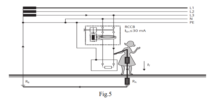
In this case we do not speak about the fault in the installation or in the kitchen appliance, but there is a possibility of un-intentional direct touch of live conductor. It is important to know that from the experiments, standards and literature in the past, there is a lot of knowledge regarding the influence of electric current on human body. Generally, we can say that the current flowing through the body which is equal or less than 30mA will cause no harmful consequences on human body. Nevertheless, for children and older people there is a strong recommendation for the electric current through the body should not exceed 10mA. That’s why there is a strong recommendation to use RCCB with 10mA rated residual current in hospitals, kindergarten and other living areas with sensitive persons.


5. RCBO as combination of MCB and RCCB


RCBO is an abbreviation for “Residual Current Breaker with integral Over-current protection”. Basically is a technical combination of two products, namely MCB and RCCB. That means, one product can provide all protection functions:

- over-current protection, meaning overload and short-circuit, the same as MCB

- fault protection with residual current behaviour, the same as RCCB

- Additional protection in case of direct touch of live parts, the same as RCCB with 30mA rated residual current.

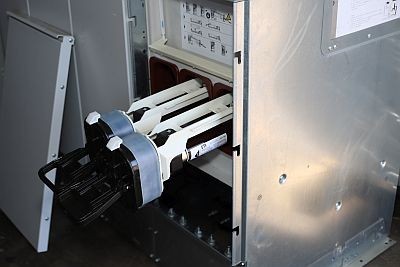
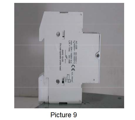
There are some construction solutions on the market, how to make the combination of MCB and RCCB to get RCBO, but the best solution for an RCBO is a compact, one-module RCBO, which is presented on the Fig.6.


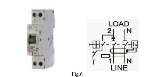
Such RCBO can provide excellent technical behaviour with following data:

- rated current: 6, 10, 13, 16, 20, 25A

- time-current characteristics: B, C

- rated short-circuit capacity: 6kA

- current limiting class: 3

- rated residual current: 10mA, 30mA

- type of residual sensitivity A

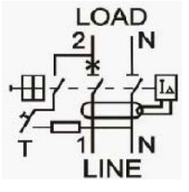
- wiring diagram switched neutral conductor, N-pole on the right,

- dimensions, width 18mm, same size as 1-pole MCB

- mode of operation: voltage dependent,

- minimum operating voltage 90V

- standard IEC 61009


5.1. How to use such RCBO?

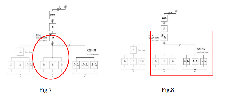
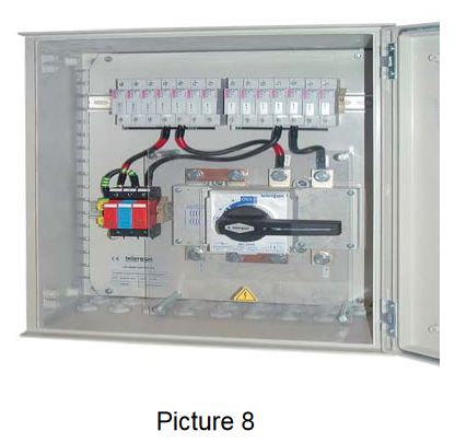
This RCBO is the best solution for additional protection in new installation, as well as in existing ones. On figures below you can find some examples of electrical installation. First example (Fig.7) shows the standard one phase residential installation where only one RCCB is used for fault protection for the whole installation. The problem in such installation is that in case of fault the complete house will be shut down. The solution for such problem is shown on the Fig.8, where on the top of installation there is RCCB with time delay, means sensitivity, and down stream in specific areas there is a RCBO with 30mA or 10mA for additional protection.


Following example below on Fig 9 shows even better situation where an existing small distribution box is altered and instead of three MCB’s, three RCBO’s are mounted in the same box (Fig.10).


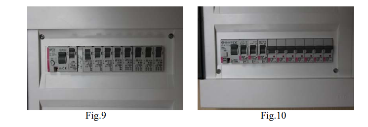
What is the benefit of such reconstruction?:

- excellent additional protection in case of direct touch of live parts,

- use of the same size of the distribution box,

- no shut down of a complete apartment in case of the fault,

- low cost for high level of protection,


6. SUMMARY of RECOMMENDATIONS


At the end of this article, we offer some recommendations how and which type of RCBO should be used in order to provide excellent protection for perfect cost-benefit ratio:

- In case of socket outlets: use C characteristics of RCBO,

- Use 30mA RCBO for socket outlets in all living rooms in your house,

- Use 10mA RCBO in rooms and areas with higher degree of protection (hospitals)

- It is recommended not to use more than 4 socket outlets on one RCBO,

- For 2.5mm2 conductor you can use either C16A or in some cases C20A RCBO,

- Upstream always use time delay, that is, selective RCCB,

- Enjoy your life well protected by RCBO’s


Utility-scale Battery storage system

Utility-scale Battery storage system

Utility-scale Battery storage system

Battery storage system is a system of serial and parallel-connected battery cells. In a battery rack are serial-connected battery modules and in battery array are parallel-connected battery racks. Battery racks are usually containerized and electrically combined inside d.c. combiner boxes, protected with fuse-links. Battery containers are then connected to the battery inverter, electically combined in an inverter d.c. combiner box protected with fuse-links.

Anže Jerman
Product manager  
FuseSpline - New software tool

FuseSpline - New software tool

New software tool called FuseSpline, helps users select the suitable HV fuse-links for protection of power transformers, motors or compensatory batteries.

The process of selecting the suitable protective devices in electrical installations is very important and must always be carried out professionally. This is especially true for the high voltage range, ie voltages higher than 1.000V.

Viktor Martinčič
Product manager for fuse systems, Chairman of IEC technical committee for fuses TC 32 
Smart home of tomorrow - with ETI protection devices

Smart home of tomorrow - with ETI protection devices

Smart home of tomorrow - with ETI protection devices

ETI is a part of all-Slovenian project that brings together individual, recently developed and technologically advanced, yet complementary, solutions of 12 Slovenian companies in a completely new and integrated solution that will enable the construction of a sustainable, smart, interconnected, user-friendly, advanced and healthy living environment.

Matija Strehar
 R&D manager for electrotechnical products

 home1

Your basket is empty.