Selectivity of Protection with NH Fuse - Links
Selectivity of protective devices is a crucial factor to consider when designing low-voltage installations. The goal of selectivity is to minimize the impact of faults. When a fault occurs, only the affected part of the installation should be disconnected, while the rest of the system remains in operation.
Protection is considered selective—whether against short-circuits or overloads—if only the faulty section of the electrical installation is interrupted. This blog post first explains the difference between overloads and short-circuits and then explores how to ensure proper selective protection using NH fuse-links.
Overloads and Short-Circuits
An overload occurs when the current flowing through a conductor or cable exceeds its permissible continuous current-carrying capacity. This typically happens when too many devices are connected to the same circuit at once.
A short-circuit, on the other hand, occurs when two points of different potential in a circuit come into contact through a path of very low impedance, resulting in a sudden surge of current.
The size of short-circuit currents in low-voltage networks depends mainly on:
The supply transformer, including its inductive and resistive impedances
The impedance of cables and conductors between the transformer and the loads
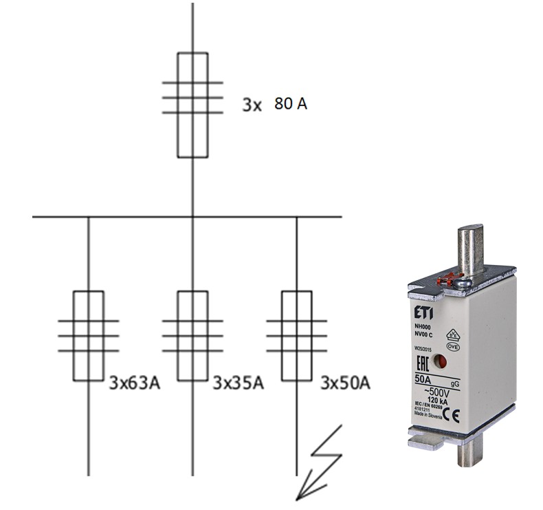
Short-circuit currents are highest at the transformer terminals and decrease with distance along the distribution network. For example, the current at a main distribution board (RG) will be lower than at the transformer, and even lower at a downstream sub-distribution board (R).
In addition, three-phase short-circuits (L1–L2–L3) typically produce higher currents than single-phase short-circuits (L–N).

Picture 1: short-circuit in a low-voltage installation
I-t Characteristic of NH Fuse-Links
An NH fuse-link’s I-t characteristic (current-time characteristic), also known as the cut-off characteristic, defines the disconnection time as a function of the expected current.
For example, Figure 2 shows the I-t curves of two ETI NH-type gG fuse-links:
NH 50 A gG (blue, lower curve)
NH 80 A gG (green, upper curve)
If an overload current of 150 A occurs, the 50 A NH fuse-link disconnects in about 8 seconds, while the 80 A NH fuse-link disconnects in about 976 seconds.
This demonstrates how the lower-rated NH fuse-link reacts significantly faster.
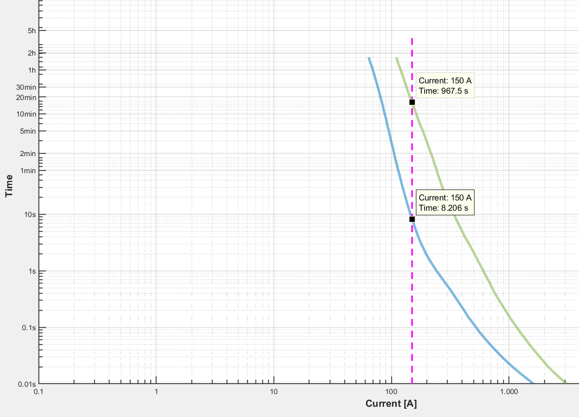
Picture 2: I-t characteristics of NV 50 A gG and NV 80 A gG fuse-links
Selectivity in Overload Protection
Selectivity between NH fuse-links under overload conditions is evaluated using their I-t characteristics for operation times above 0.1 s.
Because this post focuses on overcurrent protection of cables and conductors, we’ll consider gG-type NH fuse-links, which are suitable for general use and protect circuits across the full current range.
In the example above, if two NH fuse-links rated 80 A and 50 A are connected in series and a current of 150 A flows:
The 50 A NH fuse-link disconnects in ~8 s
The 80 A NH fuse-link would disconnect in >900 s
The downstream (50 A) NH fuse-link has a lower-lying I-t curve and therefore operates faster, ensuring that only the fuse closest to the load disconnects. This guarantees selectivity under overload conditions.
Selectivity in Short-Circuit Protection
When dealing with very high overload or short-circuit currents, where disconnection occurs in less than 0.1 s, it is necessary to consider the pre-arcing energy (also known as the pre-arcing joule integral I²t) and the total (or operating joule integral) I²t of the NH fuse-links.
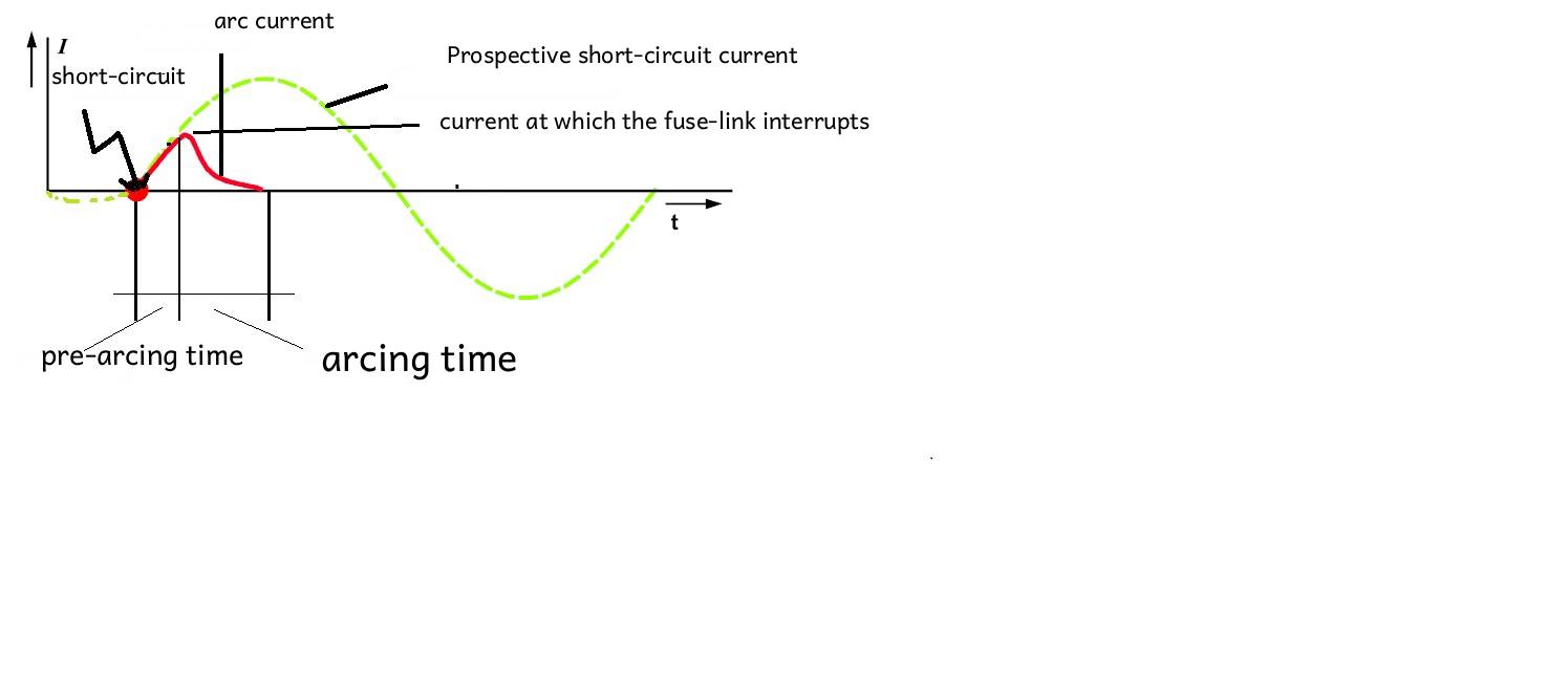
At extremely high fault currents, an NH fuse-link may disconnect in less than 5 ms—sometimes even during the first half-wave of the current. The energy passing through the fuse during this brief period is measured by the Joule integral (I²t).
Pre-arcing I²t: energy up to the point when the NH fuse-link element melts
Total I²t: energy up to the complete interruption of the current (including arc-extinction time)
For selectivity, the total I²t of the downstream (smaller) NH fuse-link must be lower than the pre-arcing I²t of the upstream (larger) NH fuse-link. Fuse manufacturers, including ETI, provide these values in their catalogs.
However, comparing I²t values can be complex for users and even for electrical professionals. Therefore, a practical rule applies:
For NH fuse-links of the same utilization category (e.g., gG) with rated currents ≥ 16 A, selectivity is ensured if the ratio of the upstream to downstream fuse ratings is at least 1.6 : 1.
This means the rated currents of two series-connected NH fuse-links must differ by at least two standard current steps.
For example:
With 80 A upstream and 50 A downstream, the ratio is 1.6, so selectivity is achieved.
If the upstream NH fuse-link were 63 A instead of 80 A, the ratio would be less than 1.6, and selectivity would have to be checked by comparing the I²t values.
Key Takeaways
Selectivity minimizes downtime and increases system safety by isolating only the faulty part of an installation.
Overload selectivity can be checked using the I-t curves: the downstream NH fuse-link must operate faster.
Short-circuit selectivity depends on the I²t energy values: the downstream NH fuse-link’s total I²t must be lower than the upstream NH fuse-link’s pre-arcing I²t.
As a rule of thumb, selectivity is guaranteed when the rated current ratio of the upstream to downstream NH fuse-links is ≥ 1.6 : 1.
By understanding these principles, installers and designers can improve the reliability and safety of low-voltage installations protected by NH fuse-links.
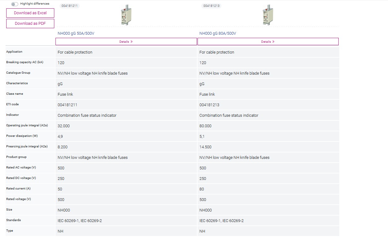
Table: comparison of the technical data of NV 50 A and NV 80 A fuse-links

