


Reactive Power Compensation
Power factor correction is one of the best investments to reduce energy costs with a short payback. In a large number of cases, the design and dimensioning work has been made more difficult by the fact that, in a company´s internal low-voltage installation, and also in the medium-voltage supplying it, the proportion of network harmonics has grown increasingly over the last few years.
Power converters, electronically controlled drives, static frequency converters, televisions and computers feed harmonic currents into the supply network. These harmonics might be amplified by the network impedances and capacitors installed. The freedom from harmonics also minimizes interference with other devices being powered from the same source.
Low voltage products for better power quality and improved network efficiency.
New !!!Informative calculation of savings with the use of automatic power factor correction banks. | |||
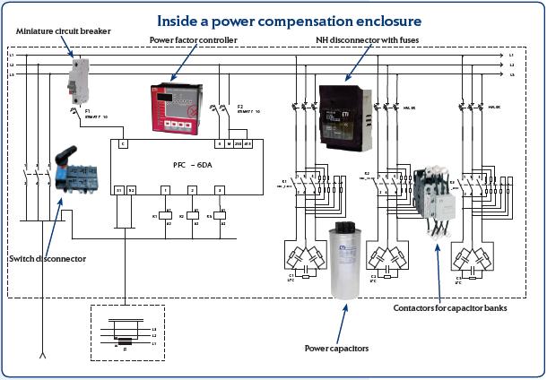
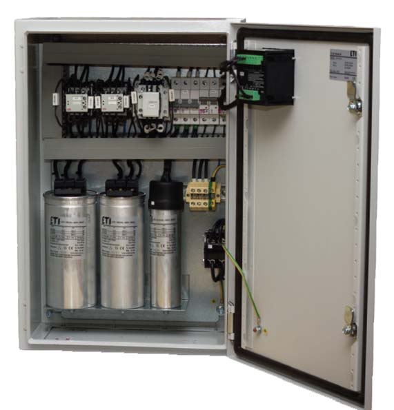
ETI Prostik power compensation equipment (enclosures) helps customers improve performance through energy savings and better power quality. With our products and solutions, customers save money and reduce the environmental impact of their operations.
We offer a wide range of power compensation equipment for low voltage levels. We analyse your needs and engineer the right solutions for optimal efficiency and economy.
Key Benefits:
- Reduce harmonics
- Compact solutions
- Lower losses
- Improved Power Quality
- Money savings
Power factor
Power factor is a way of describing how efficiently electrical power is consumed.
Power factor correction shapes the input current of off-line power supplies to maximize the real power available from the mains. Ideally, the electrical appliance should present a load that emulates a pure resistor, in which case the reactive power drawn by the device is zero. Inherent in this scenario is the absence of input current harmonics - the current is a perfect replica of the input voltage (usually a sine wave) and is exactly in phase with it. In this case the current drawn from the mains is at a minimum for the real power required to perform the needed work, and this minimizes losses and costs associated not only with the distribution of the power, but also with the generation of the power and the capital equipment involved in the process.
Power factor correction is simply defined as the ratio of real power to apparent power, or:
PF = Real power (expressed in Watts) / Apparent Power (expressed in VA),
where the real power is the average, over a cycle, of the instantaneous product of current and voltage, and the apparent power is the product of the rms value of current times the rms value of voltage. If both current and voltage are sinusoidal and in phase, the power factor is 1.0. If both are sinusoidal but not in phase, the power factor is the cosine of the phase angle. In elementary courses in electricity this is sometimes taught as the definition of power factor, but it applies only in the special case, where both the current and voltage are pure sine waves. This occurs when the load is composed of resistive, capacitive and inductive elements and all are linear (invariant with current and voltage).
 |

Catalog |
|
For additional information please contact:
Commercial and Technical info:
|