

Semiconductors protection
General information
Fuses are the oldest protective devices in the electrical industry. Because of the advantageous features, fuses have
been and are used in an extensive fields of applications – one of them is protection of semiconductor devices
(diodes, thyristors, power transistors, GTO) in current and frequency converters. Semiconductor devices are being
produced with high maximum continuous currents and peak inverse voltages. Unfortunately, that devices still
have poor overload capacities and continue to need sensitive and fast-acting protection.
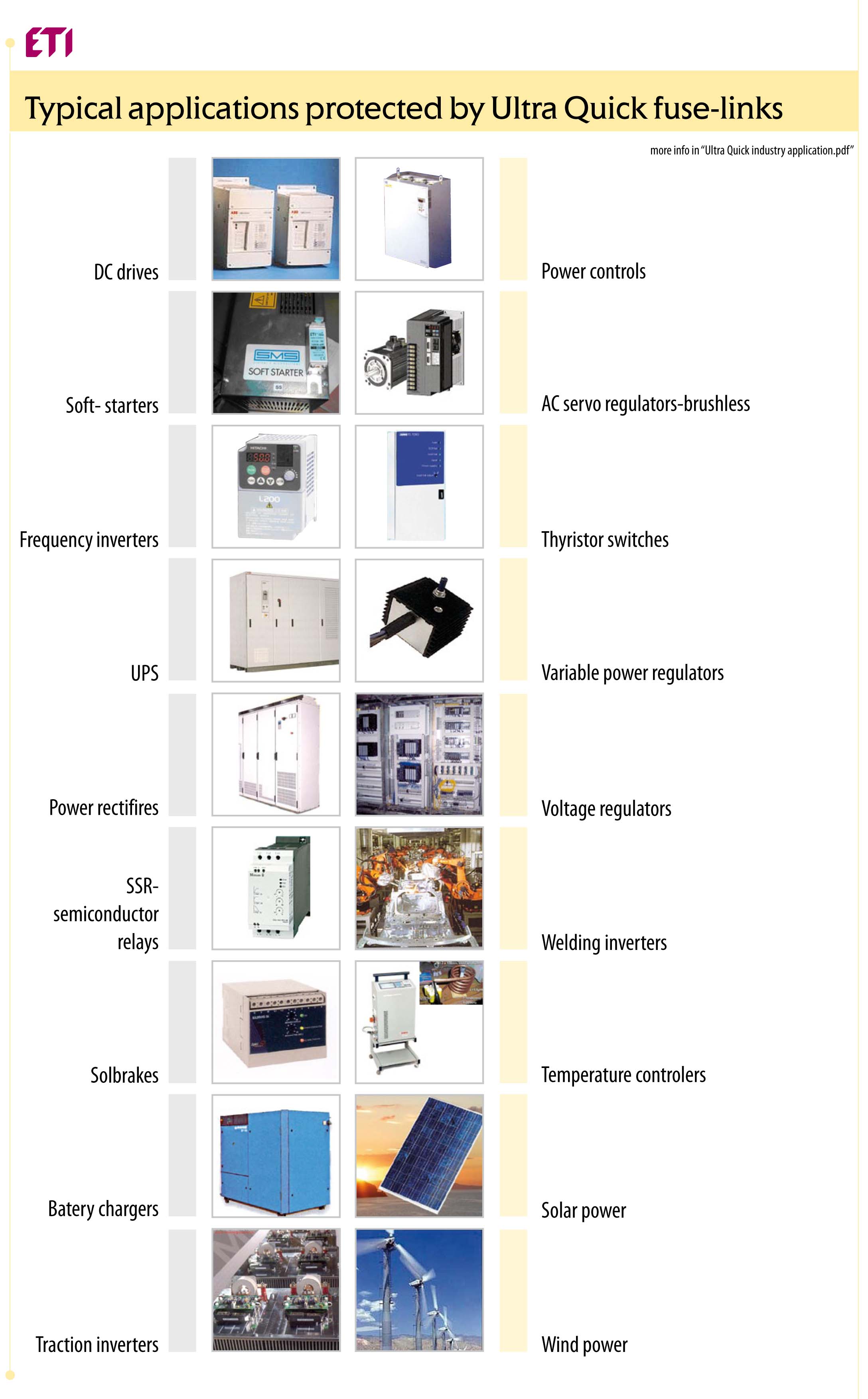
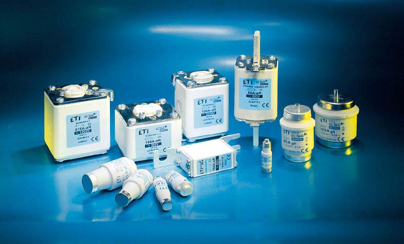
ETI fuses for semiconductor protection series ULTRA-QUICK are optimal solution for the protection of power
semiconductors.
General informations about fuse marking
Fuse marking consists of two letters, where the first letter describes the breaking ranges
a - partial range
Opearates by all currents between the lowest current indicated on its operating time current characteristic and its
rated breaking capacity.
g - full range
Opearates by all currents which cause the melting of the fuse element up to its rated breaking capacity
The second letter describes the applications (characteristics or utilization category).
G – mainly for conductor protection
B – mining equipment
M – motor circuit and switching devices protection
R – semiconductor protection
Tr – transformers protection
The combination of “breaking ranges” and “applications” indicate many combinations describes in standards and
technical report IEC 60269-5 “Application-guide for low voltage fuses”
gG: Full range - general application, mainly for conductor protection
aM: Partial range (back-up) - short-circuit protection of motor circuit
gR, gS: Full range - semiconductor protection
aR: Partial range (back-up) - semiconductor protection
gB: Full range - mining equipment protection
gTr: Full range - transformer protection
Standard
ETI fuses for semiconductor protection series “ULTRA-QUICK” comply with the IEC 60269 and VDE 0636 series
standard. A list of the standards for characteristics and dimensions is included below:
• IEC 60269-4: Supplementary requirements for fuselinks for the protection
of semiconductor devices
• IEC 60269-4-1: Examples of standardized fuses
• IEC 60269-3-1: Supplementary requirements for fuses for use by unskilled
persons (fuses mainly for householdand similar applications)
• IEC 60269-2-1: Supplementary requirements for fuses for use by authorized
persons (fuses mainly for industrial application) for the protection of
semiconductor devices
• DIN 43 620, DIN 43 653
• VDE 0636-201 Niederspannungssicherungen (NH-System)
• DIN EN 60269-4, VDE 0636 Teil 40 Niederspannungssicherungen
Teil 4: Zusätliche Anforderung an
• BS 88 Part 4
Fuses for semiconductor devices protection
Fuse-links as protective equipment for semiconductors should ensure that the following conditions are met:
- Interruption should be effected quickly enough to prevent damage to other devices
- Interruption should take place before damage to semiconductor devices – quick
action
- High rated breaking capacity
- High d.c. switching capacity
- High current limitation
- Operation of the protective equipment should not cause unacceptably high
over-voltages to be impressed on any of the semiconductor devices – low arc
voltage
Selecting the fuses for semiconductor protection (FSP)
What the user should know about FSP to be able to select the best FSP for his special purpose?
In practice, there exist no common regulations covering FSPs, except IEC60146-6 „Applications guide for the
protection of semiconductor convertors against overcurrent by fuses”. The object of this report is to advise on the
specific fuse features and on the specific convertor features which are to be observed to ensure correct application
of FSP in convertors, and to give specific recommendations for trouble-free operation of convertors protected by
fuses.
Before the fuse selection the user must be fully aware of the conditions under which the FSP is to function. This
applies to normal service conditions as well as to conditions during fault. Here is few basic suggestions for FSP
selection:
A: The load current through the semiconductor (Isem) should be lower or equal as the rated current of the selected
fuse-link (Inv). For continuous duty the FSP can withstand this current indefinetly. In case of pulsed current, the
user should consult ETI.
Isem ≤ Inv
B: The operating voltage on the semiconductor (Usem) should be lower or equal as the rated voltage of the fuselink
(Unv). Consult ETI with respect to a.c. and d.c. applied voltage, time constant and power factor.
Usem ≤ Unv
C: The operating (pre-arcing + arcing) I2t values of the selected fuse-link (I2topv) should be lower than I2t of the
semiconductor (I2tsem). Consult ETI with respect to parallel operation, discrimination and loss of coordination at
higher fault levels
I2topv < I2tsem
D: For other current rating, which are not included in this catalogue, please consult ETI R&D department.